What prevents a 100,000-ton steel giant from snapping in rough seas?
Prompted by A NerdSip Learner
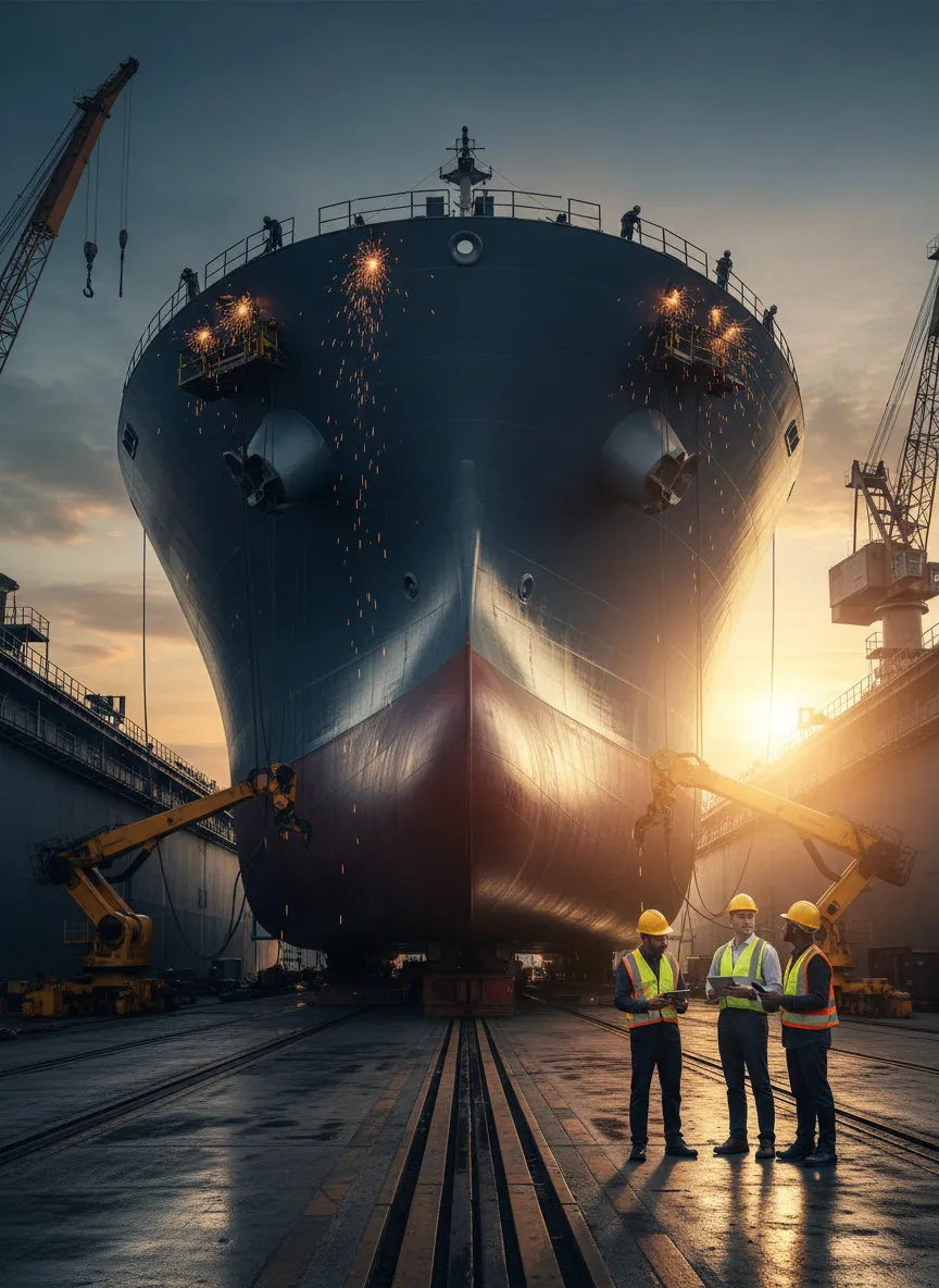
Master the core structural and system design of modern ships.
Welcome to a look at a pivotal moment in naval architecture history! While we all know the speed advantages of the WWII Liberty Ships, the transition from riveting to all-welded hulls unveiled catastrophic lessons in metallurgy. In a riveted hull, a crack stops at the edge of the plate; the joint acts as a natural crack arrestor. However, the early monolithic welded hulls allowed cracks to propagate instantaneously across the entire ship girder.
The culprit wasn't just the welding technique, but the steel's ductile-to-brittle transition temperature. In the frigid North Atlantic, the steel became glass-like. Engineers had to rapidly learn that high stress concentrations at hatch corners—combined with residual welding stresses—required a fundamental rethink of material toughness (Charpy V-notch testing) and design details.
Today, we mitigate this through rigorous stress relieving and using varying grades of steel (like Grade E for sheer strakes and bilge keels) to ensure ductility remains high even in freezing conditions. It is a fascinating reminder that structural continuity is a double-edged sword!
Key Takeaway
The shift to welding required mastering the ductile-to-brittle transition temperature to prevent catastrophic crack propagation in monolithic hulls.
Test Your Knowledge
In the context of early welded Liberty Ships, what was the primary metallurgical cause of hull failure in cold waters?
Let's dive into the hydrodynamics of the bulbous bow. You likely know it reduces drag, but let's explore the *interference* principle. The bulb generates its own wave system. Ideally, the trough of the bulb's wave coincides with the crest of the bow wave, creating destructive interference that flattens the water surface and reduces wave-making resistance ($ ext{R}_w$).
However, this is highly sensitive to the Froude number ($ ext{Fn}$). A bulb optimized for a service speed (design draft) can actually *increase* resistance when the ship creates a different wavelength at slower speeds (slow steaming) or ballast drafts. This is why modern designs often feature 'vertical' stems or gooseneck bulbs optimized for a range of operating profiles rather than a single peak speed.
Furthermore, on fuller forms like tankers ($ ext{C}_b > 0.8$), the bulb acts less on wave cancellation and more on smoothing the flow around the bilge, mitigating flow separation and ensuring better wake quality into the propeller disc. It is a brilliant example of fluid dynamics meeting practical compromise.
Key Takeaway
Bulbous bows function via destructive wave interference, but their efficiency is strictly tied to specific Froude numbers and draft conditions.
Test Your Knowledge
For full-form vessels like Supertankers (high block coefficient), what is a secondary but critical function of the bulbous bow?
Designing for LNG carriers requires mastering extreme thermal physics. When transporting natural gas at -163°C, standard steel would shatter. We principally see two competing technologies: the Moss-Rosenberg (spherical) system and the Membrane (GTT) system.
The Moss system uses independent aluminum alloy spheres. They are robust and immune to sloshing damage, but they have a poor volumetric efficiency—you waste a lot of hull space. Enter the Membrane system, specifically the GTT No. 96 or Mark III designs. These use the hull itself as the supporting structure, lined with insulation and a primary barrier.
The genius lies in the material: Invar (36% nickel steel). Invar has a coefficient of thermal expansion that is effectively zero. This allows the membrane to be welded flat without needing expansion joints to handle the thermal shock of loading cryogenic cargo. While membrane ships maximize cargo capacity (better for spot rates), they are more susceptible to sloshing impact pressures in partial loading conditions, presenting a unique operational constraint for the master.
Key Takeaway
Invar's negligible thermal expansion allows Membrane LNG carriers to maximize hull volume, unlike the volumetrically inefficient Moss spheres.
Test Your Knowledge
Why is Invar (36% nickel steel) the material of choice for the primary barrier in GTT membrane LNG carriers?
Track your progress, earn XP, and compete on leaderboards. Download NerdSip to start learning.